With the successful launch of AO-91 and AO-92 there are now more than twelve (12) active Amateur Radio Satellites or biting the Earth providing a variety of communication possibilities throughout Australia, New Zealand, South East Asia and the Pacific.
Having participated in satellite communication since the launch of Sputnik 1 in 1957, I have actively used most, if not all, the amateur radio satellites that have been launched throughout the years. In all that time I have confined my satellite operation to using my home station to great advantage. Articles elsewhere in this Blog describe some of my exploits.
Since retiring, my XYL and I are enjoying travelling especially in the National Parks throughout Australia with our 4X4 and Caravan. This activity has resulted in “ham radio” being confined to terrestrial communication. While enjoyable, it has resulted in satellite communication being “left at home” as the satellite station was hardly portable!
Over the years I have attempted to address this situation by using a variety of “hand-held” radios and antenna, with less than ideal results. With this history behind me I have decided that I need a portable satellite station to overcome this deficit in my Amateur Radio operations.
How To Proceed.
A search of the internet soon revealed that there are many portable satellite stations being used, with a mixture of equipment, by amateur radio operators around the world and I am sure a great deal of pleasure has been derived by the operators using their equipment. A great many of the solutions described use equipment that I don’t have and so I decided to design and build a system that focused on the equipment I had available.

The Design.
In designing the system it became obvious that the system needed to be totally portable, easy to assemble and when completed, needed to be simple to use!
In order to achieve the system described I was determined the design must reflect the following:
(1)The total operation needed to be based on a battery power source complete with polarised plugs, polarity protection and the ability to have a trickle charge for the battery supplied by a small solar panel.
(2)The receiver and transmitter need to be frequency agile and computer controllable to compensate for “doppler shift”.
(3)The computer must be viewable in sunlight, have sufficient ports to control the receiver and transmitter, able to run software that provides satellite predictions , have at least six hours battery life and be capable of being recharged from the main battery source.
(4)The antenna must be light weight, simple to transport and provide a minimum of 10 dBd of gain on 70cm and 6 dBd on 2m.
(5)The antenna must allow tri-pod mounting with sufficient flexibility to change its elevation and azimuth angle and polarity.
(6)The receiver and transmitter must provide multi-mode (CW, SSB & FM) operation to allow access to all of the satellites that are available.
(7)The transmitter must be capable of providing a range of sub-audible tones that are required by a number of satellites to gain access.
(8)The dials on the receiver and transmitter need to be viewable while standing or sitting behind the antenna to facilitate tuning across the band pass of the satellite (a must for linear satellite transponders).
(9)The transmitter must be capable of a power output of 5 watts if the linear transponder satellites are to be accessed.
(10)The system should be supported by a “mode J” filter to prevent “desense” of the 70cm receiver by the 3rd harmonic of the 2m transmitted signal.
(11)The tri-pod must provide a “points-of-the-compass” scale and an “elevation scale” to facilitate the pointing of the antenna on the orbit of the satellite being tracked.
While these eleven (11) points may seem to indicate a complex design, it is the minimum necessary if maximum enjoyment is to derived from the portable satellite system.
I do however, acknowledge the system could be simplified if the object of going portable is to exchange callsign, name and report. While this may be acceptable for some very low orbiting satellites, utilising a single frequency, it would preclude the operator from using satellites such as AO-07, FO-29, CAS-4 and the XW-2 series, which offer a wide range of usable frequencies and modes (CW, SSB, SSTV , FT-8 etc) providing the operator with the time to enjoy a longer QSO.
It is not my intention to discuss operators individual satellite QSO preferences in this article, but rather to identify why I assembled my portable satellite station utilising the design outlined above.
Where to begin ?
As someone once said “lets begin at the beginning”.
In the design outlined above my first concern was the overwhelming desire to make the entire system battery powered.
The Power Source.
To this end I settled on a 26ah sealed battery. With a battery of this size, it provides the luxury of allowing the equipment I intended to use, to be left running for several hours without the concern of depleting the battery. In addition I decided to include a small solar panel that would fit into the case housing all of the portable. This unit can supply a 1A trickle charge for the main battery.

Having worked portable over the years I was determined that the reverse polarity would not be an issue and so I introduced polarised plugs and sockets for all connections from the battery. The accompanying images show how this is achieved.


The Power Source and Distribution System
As a double check, I included a polarity sensing distribution system that is shown in the attached images accompanied by its schematic.
The Transceivers.
The radio equipment I decided to use were two (2) Yaesu FT-817nd Transceivers that provide 5watts output in a multi mode format.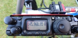 These transceivers can be computer controlled, multi-band – multi mode VFO controlled transceivers with their own internal batteries.
 In addition their screens can be easily seen in daylight and can provide different colours of screen (this proved to be a decided advantage when operating the station as explained later). These credentials match the design criteria outlined in (2) above.
The Computer.
Chasing and communicating with satellites can be quite difficult without a computer and therefore I was determined to incorporate a small laptop into the design that could be viewed in daylight (non reflective screen), have its own battery that could provide at least 6 hours of operation, 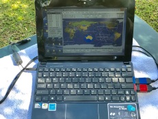 have as a minimum of 2 USB ports and be capable of running satellite prediction and control software. In addition the computer needed to be chargeable from a 12 volt source to facilitate operating for extended time periods.
My choice was an ASUS “EPC” running windows 10. The two plugs shown on the right hand side of the computer are USB ports controlling the Transceivers.
The Antenna.
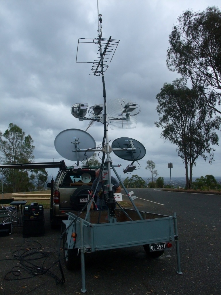
Without question the major component of the portable satellite station is its antennas. Since all of the satellite operations require a UHF and VHF antenna it is vital that each of the antennas has sufficient gain to ensure (1) the successful reception of the satellite signal and (2) sufficient radiated power to allow reception by the satellite.
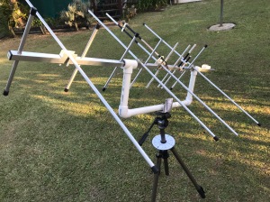
My solution to requirement was to build an 8 element UHF Yagi which provides a gain of 10dBd. The VHF Yagi has 4 elements mounted at right angles to the UHF Yagi providing a gain of 6dBd. Each antenna satisfies the link budget requirements for reception and transmission for most of the available satellites.
A Portable Antenna.
To facilitate portable operation the antenna needs to fit inside my 4X4 so it was obvious that the VHF elements had to be capable of being removed.

This process involves the VHF elements being mounted through a small aluminium channel (50mm long) and secured by a stainless PK screw. The channel has two additional holes drilled to allow two metal threads to pass through the UHF boom and fastened with wing nuts.
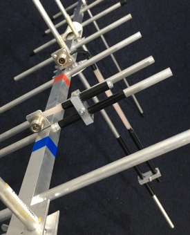

Enlarging the image will show the technique used. The reason there are three holes in the boom allow the head oh the PK screw to fit into the boom allowing the element to sit flat.
In the past I have used a technique that is simple and quick to assemble and dismantle.

Adding the last two VHF directors.
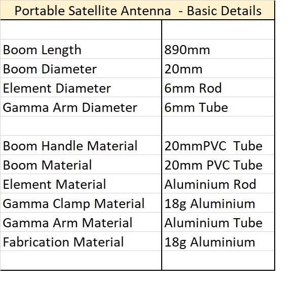
The VHF & UHF antennas were designed to be robust. The Yagi’s are based on a DL6WU design calculation and use 10mm aluminium tubing elements and a 20mm square aluminium boom. The antenna elements are mounted through the boom and are held in place using stainless steel “PK” screws.
The VHF & UHF driven elements use a gamma match for simplicity of construction.
The UHF feed line is connected using an “N” type socket while the VHF antenna uses an SO239 socket.

This shows the UHF and VHF feed points
The antenna is using plumbing PVC pipe and fittings that facilitate easy tripod mounting while creating a balanced antenna. This allows the antenna to rotate on its “X” axis and be steerable in azimuth and elevation.

Antenna mount made from Plumbing fittings and the elevation scale
Azimuth and Elevation Scales.
To simplify the usage of the antenna, there is a need for two support mechanisms
that help the operator to determine elevation and azimuth when the antenna is placed on its tri-pod.
In each case simplicity must be the key. The accompanying images show a simple compass and elevation system that allows the antenna to be pointed quickly and accurately. Both these scales were developed on the computer, printed and then laminated (weather proof!).
The elevation scale is a simple quadrant that has been glued to an aluminium bracket with its pointer made from a strip of aluminium, sprayed black and mounted using a metal thread.
The compass has a small hinge attached to the underside of the scale. The hinge was introduced to allow the legs of the tri-pod to be spread without effecting the compass.  A Velcro band attaches to the compass to the tri-pod for stability. I use the compass app on my iPhone to determine north when setting up the tri-pod and once set, directions are easily determined.
The images show that the scales are easy to read and it is quite a simple matter to follow the satellite pass.
Antenna Feed-lines.
The feed lines are routed to the rear of the antenna to ensure minimal interference to the antenna radiation pattern. The cable type I elected to use is RG-214 coax, 3 meters in length, colour coded to simplify assembly.
Transceiver, Computer and Power distribution Mounting.
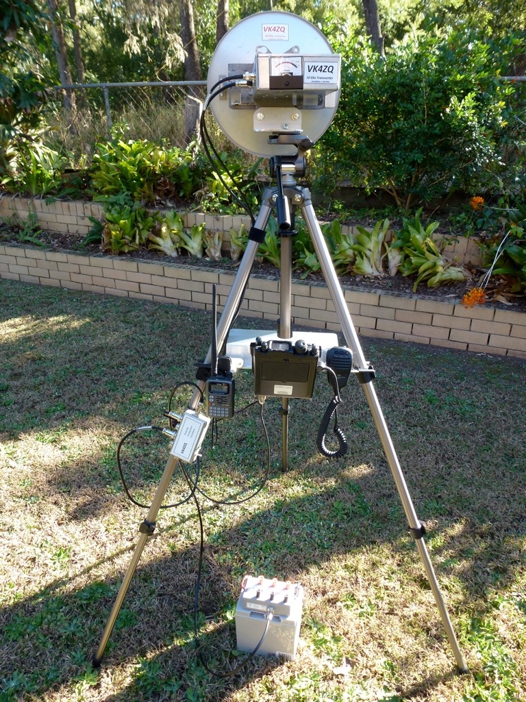
As with all portable operation, the positioning of the transceivers and the computer can make or break the entire operation.  With this thought in mind, I decided to mount the two YAESU FT-817nd transceivers and the computer on tri-pods. To achieve this, I produced a mounting bracket that locks to the tri-pod legs. The attached images show how the equipment is positioned.
The computer sits on its own tri-pod and is positioned so the screen can be seen by the operator while adjusting the antenna.
The polarity protection and distribution system also clips onto one of the tripod legs.
Improving VHF Sensitivity.
A small VHF pre-amplifier has been added to the design. This pre-amplifier can be switched out of circuit when transmitting on VHF. In addition it can simply be left switched off.
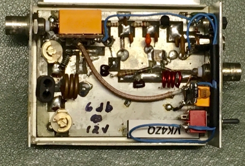
The amplifier has its gain set to 6dB and provides a noise figure of 0.1dB. A very valuable addition when working SSB through AO-07, FO-29 and the other larger satellites horizon to horizon.
Mode J Filter.
As outlined above the design calls for the use of a “mode J” filter. The filter is only active when transmitting on VHF and receiving on UHF. The filter is used to prevent the 3rd harmonic of the VHF signal radiating into the UHF receiver causing severe desensitisation when transceiving. This desensitisation can be so intense as to completely mask the satellite signal.
The simplest form of filter can be made using a diplexer that can be arranged to work as a low pass filter on VHF and a band stop filter on UHF. The VHF input of the diplexer is connected directly to the VHF output of the VHF transceiver and the UHF output of the diplexer is terminated in 50ohms. The configuration is shown in the attached circuit. The UHF output can be left unterminated however in practice I have found that terminating this output eliminates all traces of “desense” within the UHF receiver.
Arriving at the portable location.
Transporting the complete satellite station to a portable location is quite simple with all of the electronics housed in one case with the
antenna system seperate .
The antenna system comprises 2 tri-pods (one to support the antenna and the second to provide a mount for the computer), antenna mount and UHF antenna with its VHF elements removed. This makes it a simple process to store and transport the complete satellite station in the rear of my 4×4.
The assembly of the antenna system is simple as outlined earlier in the text.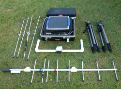
The case houses the transceivers, transceiver mount with the UHF desensitised filter, VHF pre-amplifier, power cables, microphone, feed lines, USB interface cables, polarity protection system, headphones, battery cables, DC to DC charging system for the computer, the computer, solar panel and compass disc.
All of the cables are marked with coloured tape. The tape colours I used are orange for VHF and blue for UHF for no other reason than the Yaesu transceivers can reproduce these in their screen colours making assembly of the station very straight forward.
The image shows the open case and the system components.

Making it all work!
While the portable satellite station can be assembled quickly and easily, knowing where to point the antenna and compensating for doppler shift requires another set of solutions. Thankfully the solutions can all be provided by the use of a computer with suitable software.
The software I decided to use is satPC32 ver 12.8d. I use this software in my home station with very reliable results. It has proved to be just as reliable in controlling the YAESU FT-817 nd transceivers for doppler shift correction and runs very well under Windows 10 on the ASUS computer.
I also run Orbitron ver 3.71 in radar mode. This software clearly shows the orbit of the satellite as it tracks across the sky making it very easy of point the antenna at the satellite.
NB; Orbitron is quite an old program and was written when Windows XP rained supreme. To facilitate its use with later versions of Windows make sure it is run in administrator mode to achieve full functionality.
Equipment and Software settings.
Equipment setting can make or break portable operation. It is important to make sure that all of the equipment and software are setup to “talk to each other” before going portable.
What are the variables that must be controlled?
The transceivers (VHF and UHF)
Frequency and mode will change based on computer doppler file in the tracking software
- Frequency VHF (145.5 MHz) UHF (435.5 MHz)
- Mode (FM, SSB etc)
- Power (5 watts)
- RIT (enable)
Squelch (enable – NOT RF gain)
- Control port baudrate (38K)
- Headphone switch (enabled on side of transceiver)
- Antenna port (rear so cables don’t trail across dial)
- VFO (enable)
- Battery charge time (10 HRs)
- Screen colour VHF (orange) UHF (blue).
Screen font (large enabled)
The computer

- VHF USB port (enable IRQ 3)
- VHF Port baudrate (38K)
- VHF Port identification (orange)
- UHF USB port (enable IRQ 5)
- UHF Port baudrate (38K)
- UHF Port identification (blue)
(by always plugging the cables in the same port, the setup will be set for all subsequent operation)
The computer interface
CT-62 CAT interface (2 required, one for VHF and one for UHF) colour coded as described.
The Software
SatPC32

Make sure that the software is configured in the following areas. The “Help files” clearly outline the critical settings.
- Observer profile (Call sign etc)
- Grid square (based on portable location)
- Radio interface (enable for transceivers being used)
- Control Port VHF (enable 3)
- Control baudrate (38K)
- Control port UHF (enable 5)
- Control baudrate (38K)
Doppler file (each satellite to be used needs to be set within this file)
- AMSAT name file (each satellite to be used needs to be set)
- Tone frequency ( for each satellite to be used if required)
- Prediction screen enabled (when, where and max elevation)
- Screen size (W1-W5 as required)
- Current Keps download
Orbitron

Make sure that all of the areas are filled in or the software will give erroneous.
- Observer profile (Call sign etc)
- Grid square (based on portable location)
- Tle file (for each satellite to be used)
- Not all satellites appear in the Tle file however if this file is edited to include the NASA Keps used by satPC-32 then the two programs will provide identical information.
- (http://www.amsat.org/amsat/ftp/keps/current/nasa.txt)
Keps download
Switch to “Radar screen format”
I did it my way and it worked.
I know there are many ways to setup a portable satellite station and as I mentioned in the beginning, a search of the internet will always uncover other ways to solve this problem.
Building this portable satellite station has given me hours of pleasure and a great deal of satisfaction.
Thank you for taking the time to read this article. I hope I have included sufficient information to provide you with the incentive to build a portable satellite station and participate in this ever expanding frontier of Amateur Radio.